


The AMR Revolution: Why Autonomous Mobile Robots Are Replacing Traditional AGVs
June 18, 2026
An autonomous robot without perception is just a machine moving blindly. The difference between a robot that navigates a busy warehouse safely and one that crashes into the first obstacle it encounters comes down to how well it sees, understands and reacts to its environment. This technical guide explains the core technologies that give autonomous robots their ability to perceive and navigate the real world: LIDAR, SLAM and multi-sensor fusion.
These are not abstract research concepts. They are production technologies running right now in Tosso Engineering’s T-Truck transport robots and Dobby service robots, navigating hospitals, warehouses and factories alongside human workers every day. Understanding how they work helps engineers, facility managers and technical decision makers make better choices about robotic automation.
Table of Contents
- The Perception Problem: Why Robots Need Special Sensors
- LIDAR: How Robots See in 360 Degrees
- Types of LIDAR Systems
- Understanding Point Clouds
- SLAM: Building Maps While Localizing
- SLAM Algorithms in Practice
- Sensor Fusion: Combining Multiple Data Sources
- Computer Vision and Camera Systems
- IMU and Wheel Encoders: Dead Reckoning
- Ultrasonic and Proximity Sensors
- Sensor Fusion Architecture
- How T-Truck Sees and Navigates
- How Dobby Service Robots Navigate Indoors
- Real-World Challenges and Solutions
- Frequently Asked Questions
The Perception Problem: Why Robots Need Special Sensors
Humans navigate the world effortlessly using vision, hearing, touch and spatial memory. We know where we are, where we are going and what obstacles lie ahead without conscious effort. For a robot, every one of these capabilities must be built from scratch using sensors, algorithms and computing power.
The perception challenge for autonomous robots has several dimensions:
- Localization: Where am I? The robot must determine its position within the facility with centimeter-level accuracy, continuously updating as it moves.
- Mapping: What does the environment look like? The robot needs a detailed, accurate map of walls, obstacles, pathways and landmarks.
- Obstacle Detection: What is in my path right now? Static obstacles like shelves and dynamic obstacles like people and forklifts must be detected in real time.
- Classification: What kind of obstacle is this? A wall requires a different response than a person, a temporary barrier or another robot.
- Prediction: Where will this obstacle be in 2 seconds? For dynamic obstacles, the robot must predict future positions to plan safe paths.
No single sensor can solve all these problems. That is why autonomous robots use multiple sensor types working together through sensor fusion algorithms. Wikipedia’s sensor fusion article provides a comprehensive overview of the mathematical foundations underlying these systems.
LIDAR: How Robots See in 360 Degrees
LIDAR (Light Detection and Ranging) is the primary navigation sensor for most autonomous robots. It works by emitting laser pulses and measuring the time it takes for each pulse to bounce off an object and return. By rotating the laser emitter, the sensor builds a complete 360-degree distance map of the environment.
How LIDAR Works
A LIDAR sensor contains a laser source, a rotating mirror or prism, and a photodetector. The operation cycle is:
- Emission: The laser emits a short pulse of infrared light, typically at 905nm or 1550nm wavelength
- Reflection: The pulse travels outward until it hits a surface — wall, obstacle, floor or person
- Detection: The reflected light returns to the sensor and is captured by the photodetector
- Ranging: The time of flight is measured and converted to distance using the speed of light
- Rotation: The mirror rotates to the next angle and the process repeats
A typical industrial LIDAR sensor captures thousands of distance measurements per second, creating a detailed point cloud of the environment with angular resolution of 0.25 to 1 degree and range accuracy of ±2 to ±30 millimeters depending on distance and surface properties.
LIDAR Advantages for Autonomous Robots
- Lighting Independence: LIDAR uses its own light source and works identically in bright sunlight, darkness, shadows and mixed lighting — critical for facilities with varying conditions
- Direct Distance Measurement: Unlike cameras that capture 2D images requiring complex depth estimation, LIDAR directly measures distances with high accuracy
- 360-Degree Coverage: A single rotating sensor provides complete environmental awareness around the robot
- Fast Update Rate: Modern LIDAR sensors update 10-20 times per second, providing real-time environmental awareness
- Proven Reliability: LIDAR technology is mature and proven in thousands of industrial installations worldwide
Types of LIDAR Systems
Not all LIDAR sensors are created equal. Different applications require different specifications, and understanding these differences helps in selecting the right sensor for a given robotic platform.
2D LIDAR (Single-Layer)
The most common type in autonomous mobile robots. A single laser plane scans at a fixed height, typically 20-30 cm above the ground. This captures a horizontal slice of the environment at the most relevant height for navigation — detecting walls, legs of furniture, pallets and human legs. 2D LIDAR is cost-effective, lightweight and computationally efficient.
3D LIDAR (Multi-Layer)
Multiple laser planes stacked vertically create a three-dimensional point cloud. 3D LIDAR detects overhead obstacles (signs, cables, shelves) that 2D systems miss. It is more expensive and computationally demanding but provides richer environmental data. Used in advanced autonomous robots and self-driving vehicles.
Solid-State LIDAR
Emerging technology that eliminates the rotating mechanism, using micro-mirrors or optical phased arrays instead. Solid-state LIDAR sensors are smaller, more durable and potentially cheaper, though current models have narrower field of view than rotating sensors.
Understanding Point Clouds
The raw output of a LIDAR sensor is a point cloud — a collection of thousands of points in 2D or 3D space, each representing a distance measurement at a specific angle. Understanding point clouds is essential for working with autonomous robot navigation.
Each point in the cloud has:
- Angle: The horizontal (and vertical for 3D) angle of the measurement
- Distance: The measured distance from the sensor to the reflecting surface
- Intensity: The strength of the reflected signal, which varies with surface material and color
- Timestamp: When the measurement was taken, critical for motion compensation
SLAM algorithms process these point clouds to extract features, match scans and build maps. The quality of the point cloud directly affects navigation accuracy — factors like sensor mounting position, scanning frequency and range settings all influence performance. T-Truck uses carefully optimized LIDAR configuration tuned for warehouse and factory environments.
SLAM: Building Maps While Localizing

SLAM (Simultaneous Localization and Mapping) is the algorithmic core of autonomous robot navigation. It solves a fundamental chicken-and-egg problem: to build a map, you need to know your position, but to know your position, you need a map. SLAM solves both simultaneously.
The SLAM Loop
SLAM operates in a continuous loop:
- Scan Matching: The robot takes a new LIDAR scan and compares it to the existing map. By finding the best alignment between the new scan and known features, the robot estimates its current position.
- Position Update: The robot’s estimated position is refined using the scan match result, correcting accumulated odometry errors.
- Map Update: New information from the scan is integrated into the map — new features are added, existing features are refined and confidence values are updated.
- Loop Closure: When the robot recognizes a previously visited location, the map is corrected globally to eliminate accumulated drift.
- Optimization: The entire map is optimized to minimize errors, creating a consistent, accurate representation of the facility.
Feature Extraction
Raw point clouds contain too much data for efficient matching. SLAM algorithms extract distinctive features — corners, edges, planes and clusters — that serve as landmarks for localization. These features are easier to recognize consistently across different scans and robot positions.
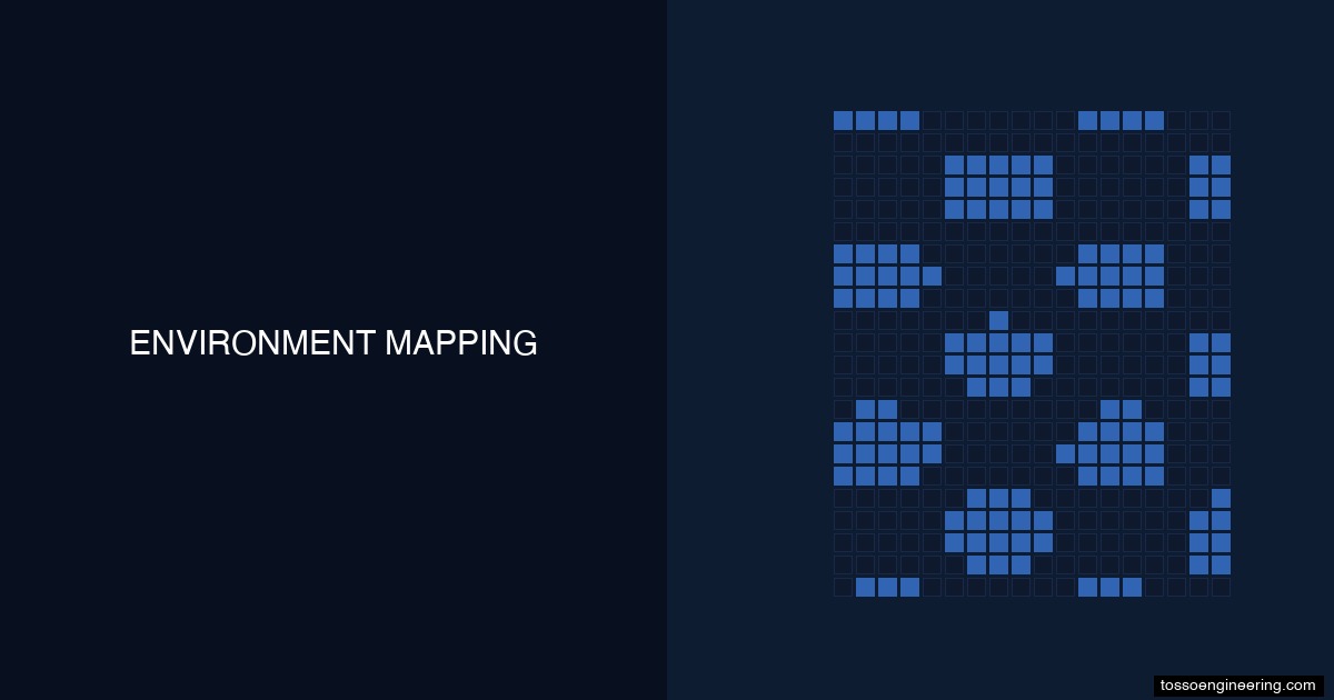
Occupancy Grid Maps
The most common map representation for autonomous robots is the occupancy grid — a 2D array where each cell represents a small area of the facility and stores the probability that the cell is occupied by an obstacle. Occupancy grids are efficient to update, easy to understand and directly usable for path planning.
SLAM Algorithms in Practice
Several SLAM algorithm families are used in production autonomous robots, each with different trade-offs between accuracy, computational cost and robustness.
Cartographer (Google)
Google’s open-source Cartographer provides real-time SLAM using LIDAR data. It supports both 2D and 3D mapping and is widely used in research and commercial applications. Cartographer uses branch-and-bound scan matching and pose graph optimization for accurate, globally consistent maps.
AMCL (Adaptive Monte Carlo Localization)
AMCL is a probabilistic localization algorithm that uses particle filters to estimate the robot’s position within a known map. It is robust against sensor noise and can recover from localization failures by spreading particles across uncertain areas. Many production autonomous robots use AMCL for localization against pre-built maps.
GMapping
GMapping is a particle filter-based SLAM algorithm optimized for 2D LIDAR. It is computationally efficient and produces accurate maps in structured indoor environments. GMapping is commonly used for initial map building in warehouse and factory deployments.
Tosso Engineering’s navigation stack combines multiple algorithms — using GMapping for initial map construction and AMCL for ongoing localization — to achieve robust performance in diverse industrial environments.
Sensor Fusion: Combining Multiple Data Sources
No single sensor is perfect. LIDAR struggles with transparent and highly reflective surfaces. Cameras struggle in low light. Encoders drift over time. IMUs accumulate errors. Sensor fusion combines the strengths of multiple sensors while compensating for their individual weaknesses.
Why Fusion is Necessary
- Redundancy: If one sensor fails or provides degraded data, others compensate. A LIDAR sensor blinded by dust does not stop a robot that also has cameras and encoders.
- Complementarity: Different sensors capture different aspects of the environment. LIDAR provides precise distance measurements; cameras provide color and texture information; IMUs provide orientation.
- Accuracy: Fused estimates are more accurate than any individual sensor. The mathematical framework of sensor fusion (typically Kalman filtering) optimally combines measurements based on their uncertainty.
- Robustness: Fusion systems can detect and reject outlier measurements from individual sensors that would otherwise corrupt the navigation solution.
Kalman Filter: The Workhorse of Fusion
The Extended Kalman Filter (EKF) is the most widely used sensor fusion algorithm in autonomous robotics. It maintains a probabilistic estimate of the robot’s state (position, velocity, orientation) and continuously updates that estimate as new sensor measurements arrive.
The EKF operates in two phases:
- Predict: Using the robot’s motion model (from wheel encoders and IMU), the filter predicts where the robot should be
- Update: When a new measurement arrives (from LIDAR, camera or other sensor), the filter corrects the prediction based on the measurement and its uncertainty
The result is a state estimate that is more accurate and more reliable than any single sensor could provide. This fused estimate is what the robot uses for navigation, path planning and obstacle avoidance.
Computer Vision and Camera Systems
While LIDAR provides the primary navigation data, cameras add capabilities that LIDAR cannot match. Computer vision enables object recognition, texture analysis, color-based identification and visual localization.
Monocular Cameras
Single cameras provide 2D images that can be processed for object detection, barcode reading, traffic sign recognition and visual odometry. Deep learning models trained on large datasets can identify people, forklifts, pallets and other objects with high accuracy.
Stereo Cameras
Paired cameras with known separation distance provide depth perception through triangulation — the same principle human vision uses. Stereo cameras create depth maps that complement LIDAR data, particularly at close range and for objects with complex geometry.
Visual SLAM (VSLAM)
Visual SLAM uses camera images to build maps and localize the robot. VSLAM is useful as a backup navigation system when LIDAR is degraded, and it provides richer map information including visual landmarks that help with place recognition.
In Dobby service robots, cameras serve dual purposes — navigation support and human interaction. The robot uses visual data to detect and track people, read signs and recognize objects while simultaneously contributing to its navigation solution.
IMU and Wheel Encoders: Dead Reckoning
Inertial measurement units (IMUs) and wheel encoders provide the robot’s basic motion estimate — how far it has moved and how much it has rotated since the last update. These sensors are essential for maintaining navigation between LIDAR scans.
IMU (Inertial Measurement Unit)
An IMU contains accelerometers and gyroscopes that measure linear acceleration and rotational velocity. By integrating these measurements over time, the IMU estimates changes in position and orientation. IMUs are self-contained — they do not depend on external signals — making them immune to interference.
However, IMU measurements drift over time due to integration of small errors. Without correction from other sensors, an IMU estimate becomes unreliable after seconds to minutes. This is why IMU data must be fused with LIDAR and other sensors.
Wheel Encoders
Optical encoders on the drive wheels measure rotation counts, which are converted to distance traveled and heading change (for differential drive robots). Wheel encoders provide high-frequency motion estimates but are affected by wheel slip, uneven surfaces and calibration errors.
Together, IMU and wheel encoders provide the motion estimate that the SLAM algorithm uses as its starting point for scan matching. The better this estimate, the faster and more reliably the scan matcher converges on the correct position.
Ultrasonic and Proximity Sensors
Ultrasonic sensors emit sound pulses and measure the echo return time. They are simple, inexpensive and detect objects regardless of color, transparency or surface texture — situations where LIDAR and cameras may struggle.
Close-Range Safety
The primary role of ultrasonic sensors in autonomous robots is close-range safety. They detect obstacles in the robot’s immediate vicinity — particularly below the LIDAR scan plane and in blind spots. When an ultrasonic sensor detects an object, the robot slows down or stops immediately.
Complementary Coverage
Ultrasonic sensors complement LIDAR by detecting surfaces that absorb or deflect laser light — glass walls, dark matte surfaces and thin objects like chair legs. In hospital and office environments where glass partitions are common, ultrasonic sensors provide essential backup detection.
T-Truck and Dobby robots use ultrasonic sensors as part of their multi-layer safety system, ensuring that no obstacle goes undetected regardless of its material properties.
Sensor Fusion Architecture
Combining multiple sensors into a coherent navigation system requires careful architectural design. The fusion architecture determines how sensor data flows, how conflicts are resolved and how the system degrades gracefully when sensors fail.
Centralized vs Decentralized Fusion
In centralized fusion, all sensor data flows to a single filter that maintains the complete state estimate. This approach is optimal but creates a single point of failure. In decentralized fusion, each sensor runs its own local filter and a master filter combines the local estimates. This provides redundancy at the cost of some optimality.
Multi-Layer Navigation Stack
Production autonomous robots typically implement a layered navigation stack. Recent research on multi-sensor fusion for autonomous navigation demonstrates how these layers interact:
- Layer 1 — Safety: Ultrasonic sensors and dedicated safety LIDAR zones for immediate collision avoidance. Runs on dedicated hardware with minimal latency.
- Layer 2 — Local Navigation: LIDAR-based obstacle avoidance and local path planning. Updates at 10-20 Hz for real-time reaction.
- Layer 3 — Global Navigation: SLAM-based localization and global path planning using the facility map. Updates at 1-5 Hz for strategic decisions.
- Layer 4 — Fleet Coordination: Multi-robot traffic management and task optimization. Runs on the fleet management server.
This layered architecture ensures that safety is never compromised by computational load from higher layers. Even if the SLAM algorithm is processing a complex map update, the safety layer continues to protect against collisions.
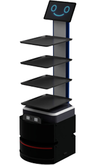
How T-Truck Sees and Navigates

T-Truck, Tosso Engineering’s autonomous transport robot, implements a complete perception and navigation system designed for the demanding conditions of industrial material handling.
Perception Hardware
- Primary LIDAR: 360-degree 2D LIDAR mounted at optimal height for detecting pallets, shelves and human legs in warehouse environments
- Safety LIDAR: Dedicated safety-rated LIDAR zones for immediate collision avoidance, independent from navigation system
- Ultrasonic Sensors: Close-range detection below LIDAR plane and in blind spots
- Wheel Encoders: High-resolution optical encoders on both drive wheels for precise odometry
- IMU: 6-axis inertial measurement unit for orientation and acceleration tracking
Navigation Software
T-Truck’s navigation stack implements the multi-layer architecture described above. During initial deployment, the robot performs an autonomous mapping run, building a detailed occupancy grid of the facility. This map is then used for ongoing localization via AMCL, with continuous map updates to reflect environmental changes.
Path planning uses a combination of global planning (A* or Dijkstra on the occupancy grid) and local planning (Dynamic Window Approach for real-time obstacle avoidance). The result is efficient, smooth trajectories that adapt to obstacles while maintaining progress toward the destination.
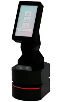
How Dobby Service Robots Navigate Indoors
Dobby service robots face a different perception challenge than industrial transport robots. They navigate crowded hospital corridors, restaurant dining rooms and retail floors where people move unpredictably and the environment changes frequently.
Human-Aware Navigation
Dobby’s navigation system includes special algorithms for human-aware path planning. The robot predicts human movement trajectories and plans paths that maintain comfortable social distances. When navigating through groups of people, the robot slows down, chooses paths that minimize disruption and communicates its intentions through movement patterns.
Dynamic Environment Adaptation
Hospital and retail environments change constantly — furniture moves, displays are rearranged and temporary obstacles appear. Dobby’s SLAM system continuously updates its map, incorporating changes within minutes. When the robot encounters a significant discrepancy between its map and reality, it flags the area for remapping.
Multi-Floor Navigation
Dobby robots operate across multiple floors, using elevators autonomously. The perception system detects elevator doors, navigates into the elevator, tracks floor changes using the IMU and exits at the correct floor. Each floor has its own map, and the robot seamlessly transitions between them.
Real-World Challenges and Solutions
Deploying autonomous robots in real facilities reveals challenges that are not apparent in controlled test environments. Understanding these challenges helps set realistic expectations and ensures successful deployments.
Featureless Environments
Long, straight corridors with smooth walls provide few distinctive features for SLAM. The robot may struggle to localize accurately in these areas. Solutions include adding artificial features (reflective markers), using IMU and encoder data to bridge featureless stretches and deploying multiple LIDAR sensors at different heights.
Dynamic Crowds
In busy environments, LIDAR scans may be dominated by moving people rather than static features. SLAM algorithms must distinguish between static and dynamic elements, using only static features for map building and localization. Advanced algorithms use multi-hypothesis tracking to handle this separation.
Changing Lighting and Conditions
While LIDAR is lighting-independent, cameras and visual SLAM are affected by lighting changes. Facilities that transition between bright daytime and dim nighttime conditions require adaptive algorithms that compensate for these variations.
Glass and Reflective Surfaces
Glass walls, mirrors and polished floors can confuse LIDAR sensors by reflecting laser pulses in unexpected directions. Ultrasonic sensors and camera-based detection provide backup in these situations. Facility preparation — adding markers to glass surfaces — is a common practical solution.
Maintenance and Updates
Maps must be maintained as facilities change. A major reorganization requires map updates, but minor changes (moved pallets, new signage) are handled automatically by the dynamic mapping system. Remote-C enables remote map management and monitoring, reducing the need for on-site technical support.
Conclusion
The perception systems that enable autonomous robots to see and navigate the real world are sophisticated but proven technologies. LIDAR provides precise distance measurement, SLAM builds and maintains accurate facility maps, and sensor fusion combines multiple data sources into robust, reliable navigation solutions.
Tosso Engineering implements these technologies in production robots that operate daily in challenging industrial environments. T-Truck navigates busy warehouses with 500 kg payloads, while Dobby service robots guide patients through hospital corridors in 20+ languages.
To learn more about how autonomous robot perception works in practice, or to discuss a deployment in your facility, book a 1:1 consultation with our engineering team. You can also explore our complete range of robotic solutions and Tossoduino IoT platform for sensor integration projects.
Frequently Asked Questions
What is LIDAR and how does it help autonomous robots?
LIDAR (Light Detection and Ranging) is a sensor that emits laser pulses and measures the time they take to bounce back from objects. This creates a precise 360-degree distance map of the environment. Autonomous robots use LIDAR as their primary navigation sensor because it works in any lighting condition, provides accurate distance measurements and updates fast enough for real-time obstacle avoidance.
What is SLAM and why is it important for autonomous robots?
SLAM (Simultaneous Localization and Mapping) is the algorithm that allows a robot to build a map of its environment while simultaneously tracking its position within that map. Without SLAM, an autonomous robot cannot know where it is or how to reach its destination. SLAM is the core technology that makes autonomous navigation possible in previously unmapped environments.
How do autonomous robots avoid obstacles in real time?
Autonomous robots use a multi-layer safety system. LIDAR continuously scans the environment and detects obstacles in all directions. When an obstacle is detected, the robot calculates an alternative path. Ultrasonic sensors provide close-range backup detection. A dedicated safety system operates independently from navigation, ensuring collision avoidance even if other systems are busy processing.
Can autonomous robots navigate in the dark?
Yes. LIDAR uses its own infrared laser light source and does not depend on ambient lighting. Autonomous robots with LIDAR-based navigation operate identically in bright daylight, dim warehouse conditions and complete darkness. Cameras used for object recognition may need supplemental lighting, but core navigation functions are unaffected.
How accurate is autonomous robot navigation?
Modern autonomous robots achieve positioning accuracy of 1-5 centimeters in well-mapped environments using LIDAR-based SLAM. Accuracy depends on the environment (feature-rich areas are more accurate), sensor quality and algorithm sophistication. T-Truck achieves centimeter-level accuracy in typical warehouse and factory conditions.
What happens when an autonomous robot encounters glass walls or mirrors?
Glass and reflective surfaces can confuse LIDAR sensors by reflecting laser pulses unpredictably. Production autonomous robots handle this through sensor fusion — ultrasonic sensors detect glass surfaces that LIDAR misses, and cameras provide additional visual confirmation. Practical solutions include applying markers or decals to glass surfaces in deployment areas.

